- 您现在的位置:买卖IC网 > Sheet目录1991 > CS53L21-CNZR (Cirrus Logic Inc)IC ADC STEREO 24BIT 98DB 32-QFN
10
DS700PP1
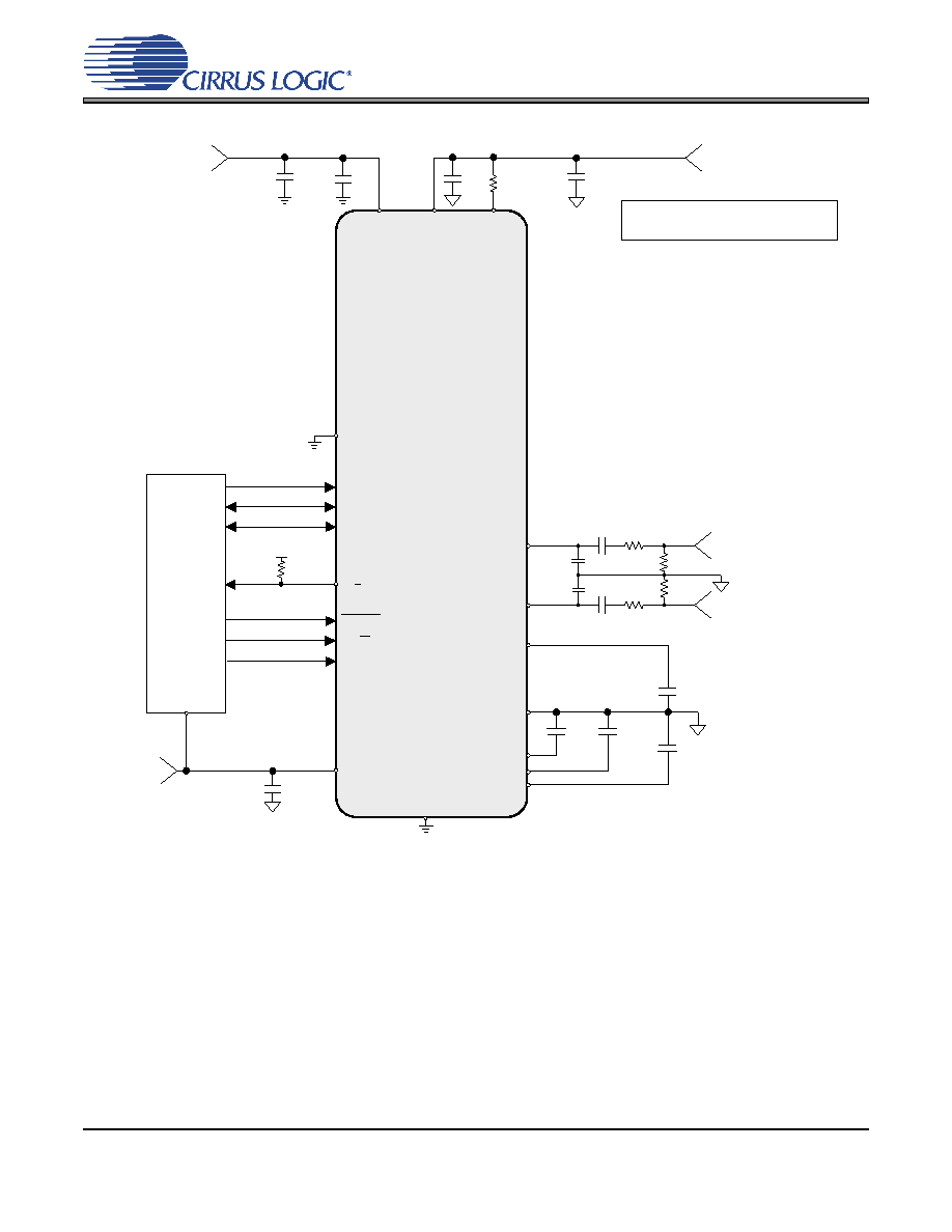
CS53L21
+1.8V or +2.5V
VQ
0.1 F
1 F
DGND
VL
0.1 F
+1.8V, 2.5 V
or +3.3V
IS/LJ
MCLKDIV2
RESET
LRCK
AGND
MCLK
SCLK
VD
* Capacitors must be C0G or equivalent
150 pF
AFILTA
AFILTB
150 pF
SDOUT/
M/S
CS53L21
1 F
**
+1.8V or +2.5V
AIN1A
Left Analog Input 1
1800 pF
100 k
Ω
100 k
Ω
100
Ω
100
Ω
AIN1B
Right Analog Input 1
*
Digital Audio
Processor
0.1 F
VA
10 F
FILT+
1 F
VL or DGND (1)
See Note 4
Note 4:
Series resistance in the path of the power supplies
(typically used for added filtering) must be avoided.
(1) Pull-up to VL (47 k
Ω ≤for Master Mode.
Pull-down to DGND for Slave Mode.
TSTN
47 k
Ω
VA_
PULLUP
Figure 2. Typical Connection Diagram (Hardware Mode)
发布紧急采购,3分钟左右您将得到回复。
相关PDF资料
CS5509-ASZR
IC ADC 16BIT SGL SUPP 16-SOIC
CS5512-BSZ
IC ADC 20BIT EXTERNAL OSC 8-SOIC
CS5526-BSZR
IC ADC 20BIT W/4BIT LATCH 20SSOP
CS5528-ASZR
IC ADC 24BIT 8CH 24-SSOP
CS5529-ASZR
IC ADC 16BIT W/6BIT LATCH 20SSOP
CS5530-ISZR
IC ADC 24BIT 1CH W/LNA 20-SSOP
CS5534-ASZR
IC ADC 24BIT 4CH W/LNA 24-SSOP
CS5534-BSZR
IC ADC 24BIT 4CH W/LNA 24SSOP
相关代理商/技术参数
CS53L21-DNZ
制造商:Cirrus Logic 功能描述:IC LW-POWER STEREO ANALOG-TO-DIGITAL ADC - Rail/Tube 制造商:Cirrus Logic 功能描述:IC ADC STEREO 24BIT 96KHZ 32QFN
CS53L21-DNZR
制造商:Cirrus Logic 功能描述:IC LW-POWER STEREO ANALOG-TO-DIGITAL ADC - Tape and Reel 制造商:Cirrus Logic 功能描述:IC ADC STEREO 24BIT 96KHZ 32QFN
CS53L30-CNZ
制造商:Cirrus Logic 功能描述:IC ADC 24BIT STER 16KHZ 32QFN 制造商:Cirrus Logic 功能描述:Audio A/D Converter ICs 4 Mic ADC 制造商:Cirrus Logic 功能描述:ADC, 24BIT, 16KSPS, I2C, QFN-32, Resolution (Bits):24bit, Sampling Rate:16kSPS,
CS53L30-CNZR
功能描述:IC ADC 24BIT STER 16KHZ 32QFN 制造商:cirrus logic inc. 系列:- 包装:带卷(TR) 零件状态:在售 类型:ADC,音频 分辨率(位):24 b 采样率(每秒):16k 数据接口:I2S 电压源:单电源 电压 - 电源:1.71 V ~ 1.89 V 工作温度:-10°C ~ 70°C 安装类型:表面贴装 封装/外壳:32-VFQFN 裸露焊盘 供应商器件封装:32-QFN(5x5) 基本零件编号:CS53L30 标准包装:6,000
CS53L30-CWZR
功能描述:音频模/数转换器 IC 4 Mic ADC
RoHS:否 制造商:Wolfson Microelectronics 转换速率: 分辨率: ADC 输入端数量: 工作电源电压: 最大工作温度: 最小工作温度: 安装风格: 封装 / 箱体: 封装:
CS53L32A
制造商:CIRRUS 制造商全称:Cirrus Logic 功能描述:Low Voltage, Stereo A/D Converter
CS53L32A-BZ
制造商:CIRRUS 制造商全称:Cirrus Logic 功能描述:Low Voltage, Stereo A/D Converter
CS53L32A-KZ
制造商:Rochester Electronics LLC 功能描述:LOW VOLTAGE A/D CONVERTER - Bulk 制造商:Cirrus Logic 功能描述: